To analyse a device’s firmware, you’ll first need to obtain the firmware. If you’re lucky, the device manufacturer has made the firmware available for download. If it’s not available, or if you don’t trust that what’s on the website is what’s on your device, you can extract the firmware from flash memory. This post outlines how to extract firmware from flash memory on a D-Link DCS-932L internet enabled security camera.
Locating the flash memory chip
An IoT device such as my security camera typically has a number of chips, each with a specific purpose. After I opened my camera, I found this:
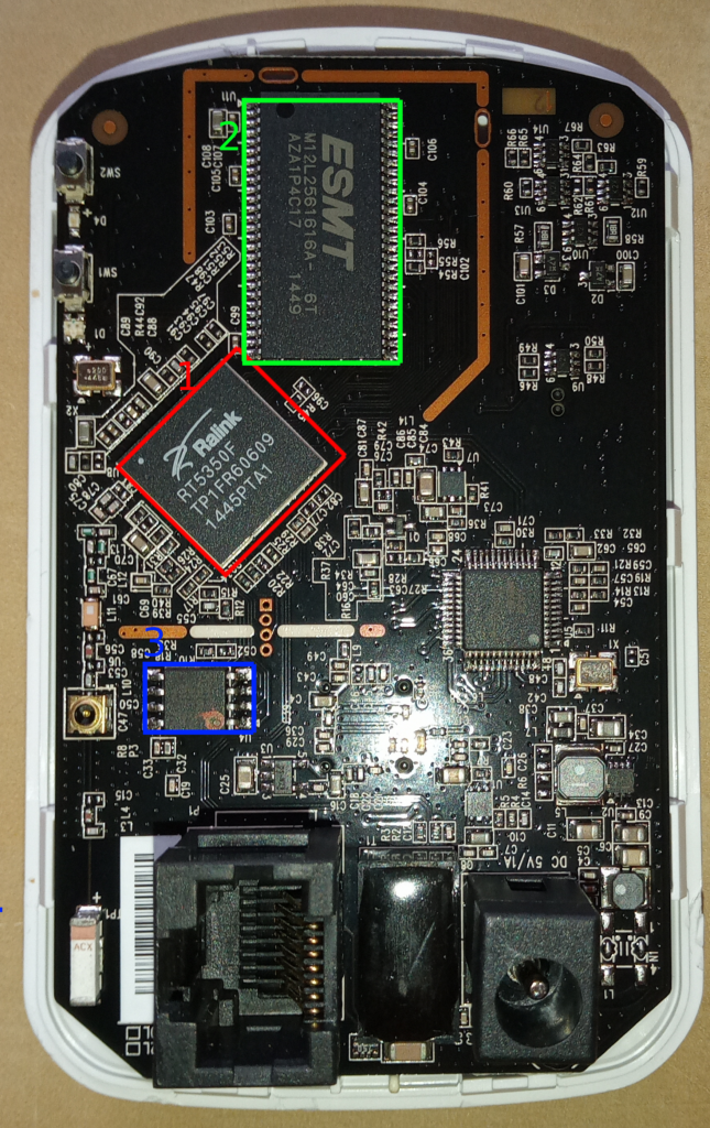
This device contains:
- Ralink RT5350F System on Chip (SoC). This is the CPU plus various network functions (ethernet, USB, wireless)
- ESMT M12L2561616A memory. This is the working RAM.
- MX25L3205D flash memory. The firmware is here.
The SoC loads the firmware from the flash memory into working RAM and boots the operating system.
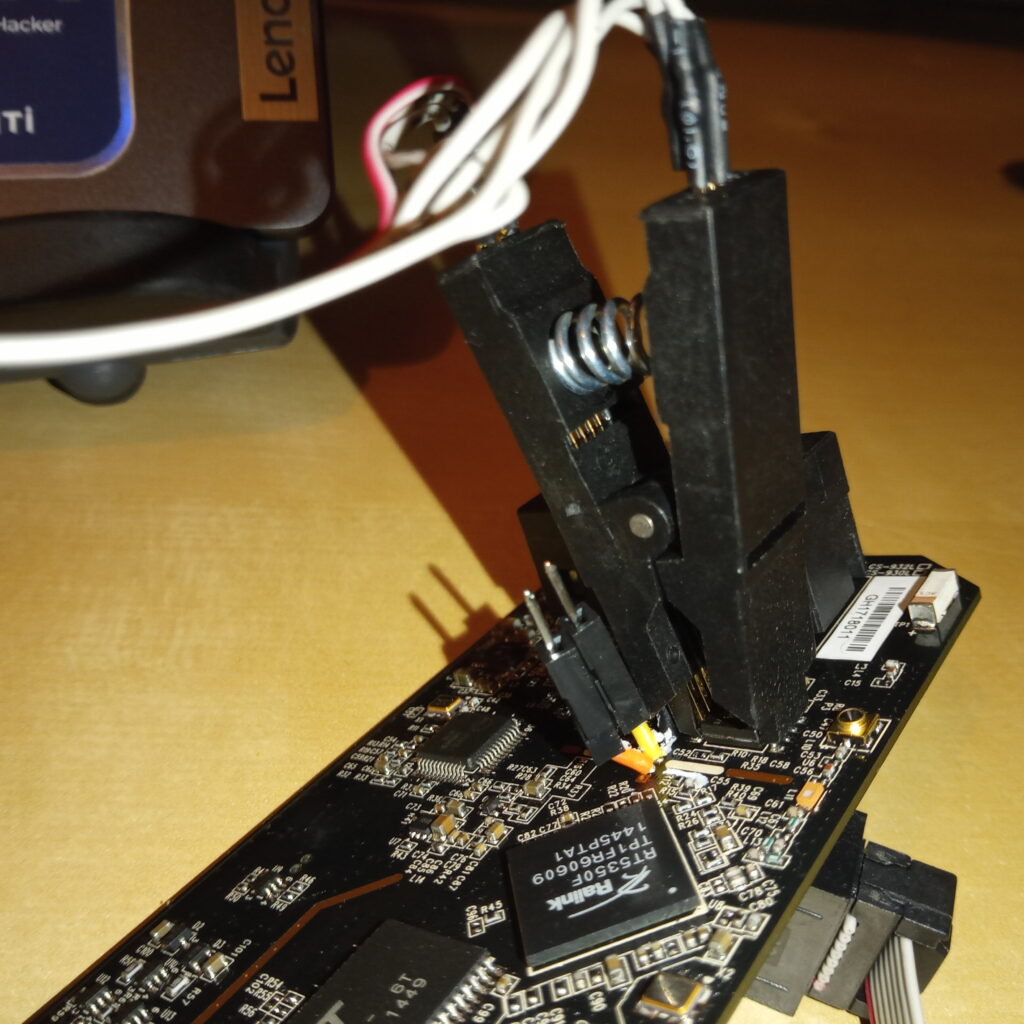
The flash memory chip is SOP-8 form factor – 8 pins, 1.27mm pitch. I have limited soldering abilities so I could not confidently work with a chip this small. Ideally I want to work with the chip without removing it from the board.
SOP-8 test clip
You can work with the flash memory chip without removing it from the board by attaching an SOP-8 test clip. This fits over the legs of the chip, making an electrical contact. You can then communicate with the chip while it is attached to the board.
You have the option of sending signals directly to the chip or attaching it to the programmer board and interfacing via USB. The latter is far easier but if you’re interested in accessing these at a low level, Ben Eater demonstrated the technique with a TV Guardian device from the 1980s in a very informative and accessible video.
I don’t want to read the data sheet for this or program my own interface so I’m using the programmer over USB.
Extract the firmware from flash memory via USB programmer
You can connect the flash chip to a laptop with the USB programmer.
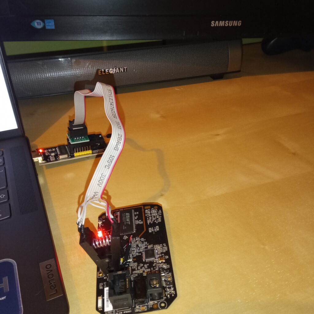
Then access the contents of the Flash ROM using flashrom:
sudo flashrom --programmer ch341a_spi -r flashrom.binThis reads from the attached ch341 programmer and writes the contents to a file called flashrom.bin. flashrom will attempt to autodetect the chip but if it can’t, it will give a list of candidates for you to choose:
Found Macronix flash chip "MX25L3205(A)" (4096 kB, SPI) on ch341a_spi.
Found Macronix flash chip "MX25L3205D/MX25L3208D" (4096 kB, SPI) on ch341a_spi.
Found Macronix flash chip "MX25L3206E/MX25L3208E" (4096 kB, SPI) on ch341a_spi.
Found Macronix flash chip "MX25L3273E" (4096 kB, SPI) on ch341a_spi.
Multiple flash chip definitions match the detected chip(s): "MX25L3205(A)", "MX25L3205D/MX25L3208D", "MX25L3206E/MX25L3208E", "MX25L3273E"
Please specify which chip definition to use with the -c <chipname> option.
The -c option specifies the chip type to be read. Mine is the MX25L3205D.
sudo flashrom --programmer ch341a_spi -c "MX25L3205D/MX25L3208D" -r flashrom.binThis takes around a minute to run and gives me a 4194304 byte (4MB) file.
Unpack the firmware with binwalk
The 4MB bin file is a binary dump of the contents of the flash chip. It’s not a particular file format. Fortunately, binwalk can find known file formats in a binary file and carve them out.
binwalk -e flashrom.binThis extracts a LZMA archive from the bin at location 0x50040. Using the -e (for extract) option will write this archive to a file named 50040. You could then use binwalk -e on 50040 to extract its contents and so on. It is often easier to use binwalk‘s recursive option (-M, --matryoshka):
binwalk -eM flashrom.binThis unpacks recursively down to a directory named cpio-root that contains the device filesystem:
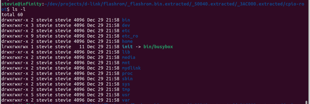
There is other stuff in the firmware including the bootloader and the ‘Emergency Room’ recovery application but often we’re most interested in the device file system. It contains lots of juicy nuggets including the /etc/passwd and /etc/shadow files, configuration and defaults and installed applications.
In the next post we’ll look at how we can use information from the firmware to access a root shell on the device.
[…] the first part of a teardown of a D-Link DCS-932L internet enabled security camera, I looked at extracting firmware from flash memory. In this second part, I look at connecting to UART and using the root shell to have a rummage about […]