Many IoT devices have a UART connector somewhere on the board. It is often used to debug the device before mass production. Sometimes there will be a nice four pin header to connect to. Other devices give you just some plated through holes ready to solder. In some cases the holes exist but the traces have been disconnected in the final layout. In any case if you can connect to it you can often obtain device logs, issue commands and sometimes access the boot loader. If you’re lucky you can get full shell access over UART.
In the first part of a teardown of a D-Link DCS-932L internet enabled security camera, I looked at extracting firmware from flash memory. In this second part, I look at connecting to UART and using the root shell to have a rummage about the camera’s file system.
Find the connector
It’s fairly easy to locate the UART connectors on the DCS-932L. When I opened it up, I found this:
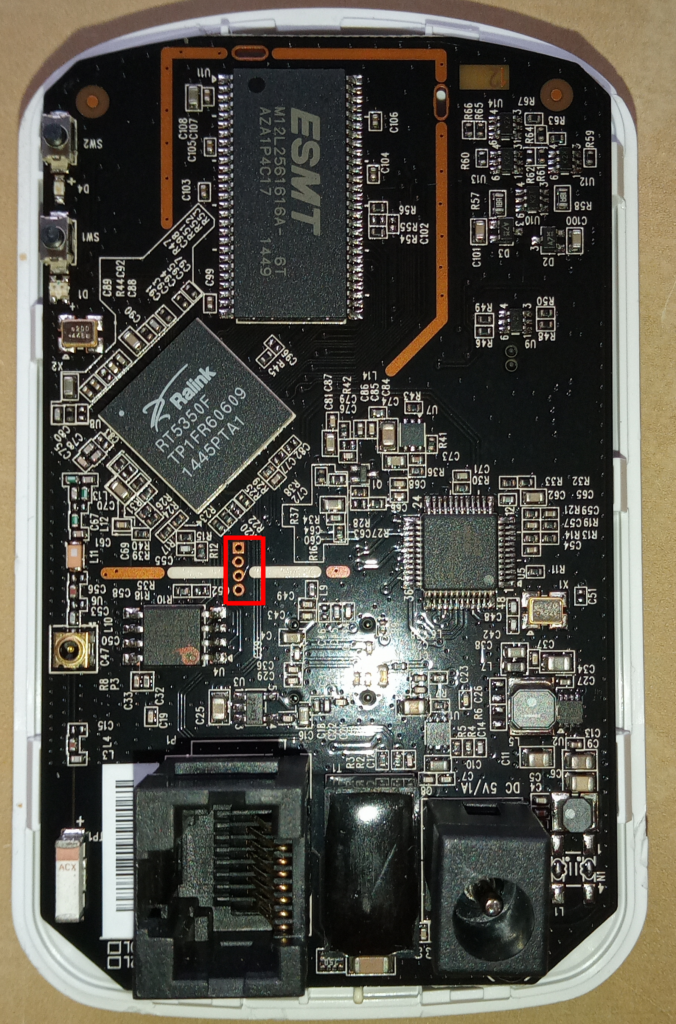
Four unconnected plate through holes right in the middle of the board. If you look from the back, it’s even more obvious:
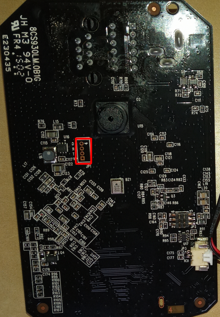
The holes are helpfully labelled (in reverse lettering) G R T V. Corresponding to the four UART lines Ground, Receive, Transmit and positive voltage. I used a multimeter to confirm this. With the board powered on, I tested that G has continuity with a ground connection elsewhere on the board and V was 3.3V. T was mostly 3.3V but occasionally dipped to 0. This is consistent with its purpose. It transmits data with a 3.3V signal but there’s not always any output to transmit.
The only snag here is that there’s no header on this connector and I don’t have a suitable size header to attach. So I ended up soldering ordinary wires to connections. A little fiddly but not a problem.
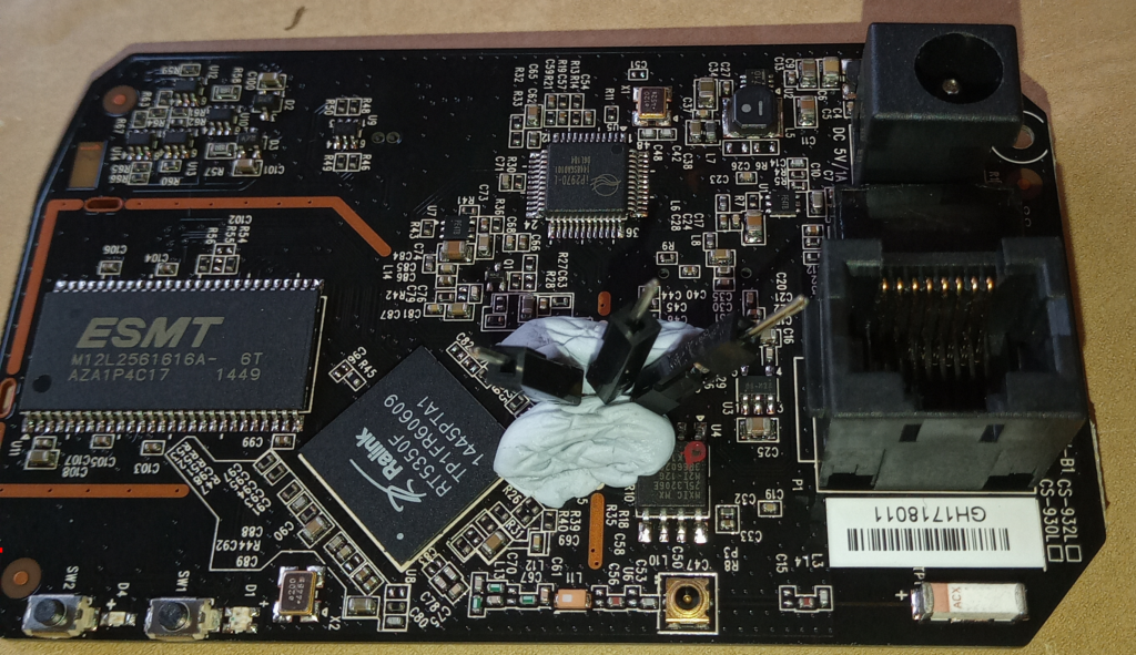
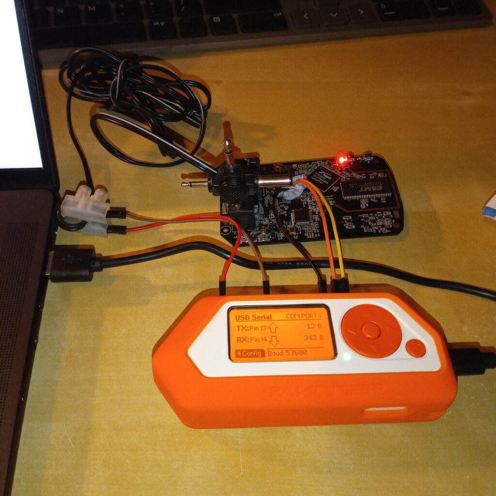
I used some blu-tack to hold the wires in place when I soldered them. The connections looked a little fragile so I just left the blu-tack in place. I used very short wires – I just wanted three pins to attach to. This was perhaps a mistake and I had to revisit this later.
Connecting to a laptop
I used an FTDI UART to USB cable to connect my new UART connections to my laptop. The cable is based on a FT232 board. You can get these in various form factors including bare boards that you solder your own connections or assembled cables with bare wires for soldering to a board. Mine has a cable with three female single pin headers so nice and easy to plug into the pins I soldered to my camera.
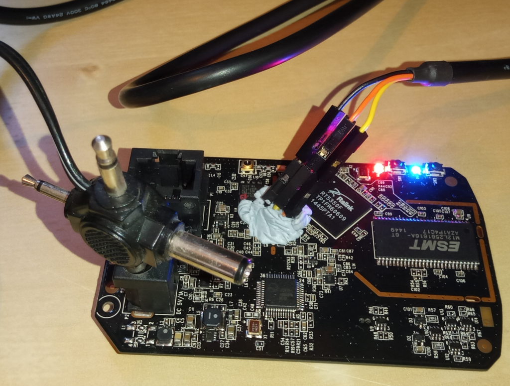
The other end of this connects to the laptop. The part I had most difficulty with was powering up the camera. It requires 5V power but didn’t come with an adapter. After fiddling about with a faulty universal power adapter (now in the bin!), I ended up powering the camera from the 5V output of an Arduino.
The other way I could have done this is with the GPIO interface of a Flipper Zero. This has the advantage that the Flipper can both interface with UART and provide 5V power but it does require a little menu diving so is overall slightly less convenient than the dedicated FTDI cable.
Boot loader access over UART
With the FTDI USB adapter connected, I launched screen and connected to /dev/ttyUSB0 (or /dev/ttyACM1 when using the Flipper Zero):
sudo screen -L -Logfile screen.$(date +%s).out /dev/ttyUSB0 57600I used -L to copy output to a logfile and used $(date +%s) to give each run a unique name. The number on the end is the device’s baud rate. It took a couple of guesses to get this right but there are only a handful of valid rates so guessing is fine. An incorrect baud rate produces gibberish but eventually I got this:
U-Boot 1.1.3

Board: Ralink APSoC DRAM:  32 MB
relocate_code Pointer at: 81fb0000
spi_wait_nsec: 42
spi device id: c2 20 16 c2 20 (2016c220)
find flash: MX25L3205D
raspi_read: from:30000 len:1000
.*** Warning - bad CRC, using default environment

============================================
Ralink UBoot Version: 4.1.2.0
--------------------------------------------
ASIC 5350_MP (Port5<->None)
DRAM_CONF_FROM: Boot-Strapping
DRAM_TYPE: SDRAM
DRAM_SIZE: 256 Mbits
DRAM_WIDTH: 16 bits
DRAM_TOTAL_WIDTH: 16 bits
TOTAL_MEMORY_SIZE: 32 MBytes
Flash component: SPI Flash
============================================
icache: sets:256, ways:4, linesz:32 ,total:32768
dcache: sets:128, ways:4, linesz:32 ,total:16384

 ##### The CPU freq = 360 MHZ ####
^M estimate memory size =32 Mbytes
^M
Signature: DCS-930 B1         932L  Release 1.12 (2016-02-25)

Please choose the operation:
   1: Load system code to SDRAM via TFTP.
   2: Load system code then write to Flash via TFTP.
   3: Boot system code via Flash (default).
   4: Entr boot command line interface.
   7: Load Boot Loader code then write to Flash via Serial.
   9: Load Boot Loader code then write to Flash via TFTP.
We clearly have good communication with UART (in one direction anyway) and the log messages already give us useful information.
First we can see that we’re launching U-Boot and an option menu is shown – we can likely interrupt the boot process and access the boot loader, its command line interface and we can send alternative code to run over TFTP (trivial file transfer protocol) or serial (UART). Second, we see some memory addresses.
I used the boot loader option 4 to access the U-Boot CLI and then dumped various blocks of memory using the md command. However, as we’ve not loaded the firmware from flash memory yet, I can’t dump the firmware this way. It is sometimes possible to access flash memory from U-Boot but not in this case as the required CLI commands have been disabled.
Despite the firmware not being loaded yet, I do see something interesting in there:
stevie@infinity:~/dev/projects/d-link/memdump$ binwalk ALL.bin

DECIMAL       HEXADECIMAL     DESCRIPTION
--------------------------------------------------------------------------------
3960          0xF78           uImage header, header size: 64 bytes, header CRC: 0xD5085968, created: 2019-01-28 08:41:52, image size: 111116 bytes, Data Address: 0x80200000, Entry Point: 0x80200000, data CRC: 0xB7373BBA, OS: Linux, CPU: MIPS, image type: Standalone Program, compression type: none, image name: "SPI Flash Image"
2188128       0x216360        U-Boot version string, "U-Boot 1.1.3"
2202512       0x219B90        HTML document header
2202858       0x219CEA        HTML document footer
2202868       0x219CF4        HTML document header
2203060       0x219DB4        HTML document footer
2203228       0x219E5C        HTML document header
2203921       0x21A111        HTML document footer
There’s a header for an uncompressed Linux OS named SPI Flash Image at address 0xF78 and some HTML detected from address 0x219B90. I believe that this is the “Emergency Room” web application that allows the firmware to be updated if the existing firmware is broken. This is what you get when you start the camera with the reset button held down. It’s a very simple webserver with a single page for uploading new firmware.
Shell access over UART
If we don’t enter an option in the bootloader menu it will boot the system from flash memory. It shows lots more log messages that gave me useful insight into the workings of the system. Eventually it shows a login prompt:
starting pid 881, tty '/dev/ttyS1': '/bin/login'
(none) login:
I tried guessing the username and password. root/root and root/<no password> didn’t work. The startup logs shows something that looks like a user id:
Welcome to^M
     _______  _______  ___     __  ____   _  _   ___^M
    |  ___  \|   __  ||   |   |__||    \ | || | /  /^M
    | |___| ||  |__| ||   |__  __ |     \| || |/  /^M
    |   _   /|   _   ||      ||  || |\     ||     \^M
    |__| \__\|__| |__||______||__||_| \____||_|\___\^M

                     =System Architecture Department=

uid: Rg23asnv6ApXz6ci
I wasn’t able to login with this either. I believe it’s an admin user for the camera’s web UI and not an OS user. Regardless, I couldn’t login with it.
No problem, I can look in the /etc/passwd and /etc/shadow files to find usernames and passwords. The passwords would be hashed but I reckon I can crack it with hashcat. Fortunately, I had already extracted the firmware from the flash chip. It’s also freely available to download from D-Link.
After unpacking the firmware, I looked in /etc and found… Nothing. There’s also an /etc_ro directory. Again, no passwd or shadow files. The startup logs are very helpful though and give a clue as to what’s happening:
*****************
*  INTERNET.SH  *
*****************
Password for 'admin' changed
The /sbin/internet.sh script is setting a password for the ‘admin’ user. And that script is in the unpacked firmware.
# setup username:password
login=`nvram_get 2860 AdminID`
if [ "$login" = "" ]; then
echo "loading default configuration ..."
sleep 3
login=`nvram_get 2860 AdminID`
fi
pass=`nvram_get 2860 AdminPassword`
echo "$login::0:0:Adminstrator:/:/bin/sh" > /etc/passwd
echo "$login:x:0:$login" > /etc/group
chpasswd.sh $login $pass
The script is reading AdminID and AdminPassword from non-volatile RAM, creating the user and setting the password. That’s very clever as it removes credentials from the publicly available firmware image and away from my prying eyes. So I now need to either read the nvram directly or find what sets values in it.
I did not find strings AdminID or AdminPassword from my memory dumps obtained from the bootloader. I did however find them in the unpacked firmware:
$ grep -r AdminID *
grep: bin/alphapd: binary file matches
grep: bin/lanconfig: binary file matches
grep: bin/ralink_init: binary file matches
etc_ro/Wireless/RT2860AP/RT2860_default_vlan:AdminID=admin
etc_ro/web/cgi/system.cgi:AdminID=%%AdminID();%%
sbin/chpasswd.sh:user=`nvram_get 2860 AdminID`
sbin/internet.sh:login=`nvram_get 2860 AdminID`
sbin/internet.sh:login=`nvram_get 2860 AdminID`

$ grep -r AdminPassword *
grep: bin/alphapd: binary file matches
grep: bin/busybox: binary file matches
grep: bin/lanconfig: binary file matches
grep: bin/gpio: binary file matches
etc_ro/Wireless/RT2860AP/RT2860_default_vlan:AdminPassword=
etc_ro/web/cgi/system.cgi:AdminPassword=%%AdminPassword();%%
grep: init: binary file matches
grep: mydlink/tdb: binary file matches
sbin/chpasswd.sh:pass=`nvram_get 2860 AdminPassword`
sbin/internet.sh:pass=`nvram_get 2860 AdminPassword`
They both show up in the /etc_ro/Wireless/RT2860AP/RT2860_default_vlan config file. In this default config, AdminID=admin and AdminPassword= (blank). Surely not…
(none) login: admin
Password:
Jan  1 00:00:28 login[869]: root login on 'ttyS1'


BusyBox v1.12.1 (2019-01-28 16:36:42 CST) built-in shell (ash)
Enter 'help' for a list of built-in commands.

# ls
bin      sys      mnt      init     etc      var      mydlink  usr
media    home     dev      sbin     tmp      lib      etc_ro   proc
# cat /etc/passwd
admin:x39bQZl/NURiM:0:0:Adminstrator:/:/bin/sh
Yes, we’re in with admin/<blank>. I could have guessed that! The password hash listed in /etc/passwd (x39bQZl/NURiM) does indeed correspond to a blank password. It appears that the internet.sh script supports loading secrets from non-volatile RAM but for this particular device in its default configuration it just uses the defaults in the config file.
What next?
After rummaging in the firmware, bootloader and shell, there are all sorts of goodies in here that might be worth further investigation.
First, an nmap scan reveals that the camera exposes port 80 and 443 for its web interface (expected) and port 8530. I’m not sure what the latter is. Perhaps its connection back to the D-Link servers?
Second, the webserver for the camera’s admin pages is quite old and has already had vulnerabilities patched. Can we do anything interesting if we have access to it?
Finally, I was only able to extract the firmware from this device by physically attaching to the flash chip. I’d like to look at doing this from the bootloader. I was able to dump the RAM from the U-Boot CLI but the flash ROM was inaccessible. U-Boot provides an sf probe command that can copy flash ROM to RAM (and hence make it available for me to dump) but this command was disabled. Could I use options available in the bootloader menu to load an alternative U-Boot build that allows access to the additional commands I want?
[…] the next post we’ll look at how we can use information from the firmware to access a root shell on the […]